


How to Make Job Drawing for EagleTec CNC Wood Lathe | CNC Wood Lathe Tutorials
Our wood lathes can directly read drawings in format of ***.dxf, so generally we use AutoCAD software to make design drawings. As long as we have DXF drawings, we can make the machine to turn, no need to create toolpath via ArtCAM software any more. So it becomes pretty easy to learn how to make the drawing for EagleTec wood lathe machine. Okay, now we start:
Let’s say we have a square wood block with size 60x60x150mm, and we want to make a column from it by EagleTec automatic wood lathe machine. Please see drawing below, the side - length of the four sides of the wood is 60mm, and accordingly, the diagonal length is 84.85 mm. Because for the square, the diagonal length is 1.414 times the side - length. (60x1.414=84.85mm)
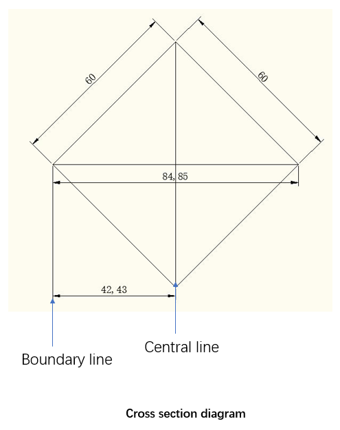
When drawing, we only draw the part from the center line to the left, which is the left half. Our design is to be created in the space between the left boundary line and the center line. The corresponding size of this space is half of the diagonal, that is, 42mm, and the deepest part of the workpiece must be less than 42mm, otherwise the wood will be break. Please refer to drawing below:
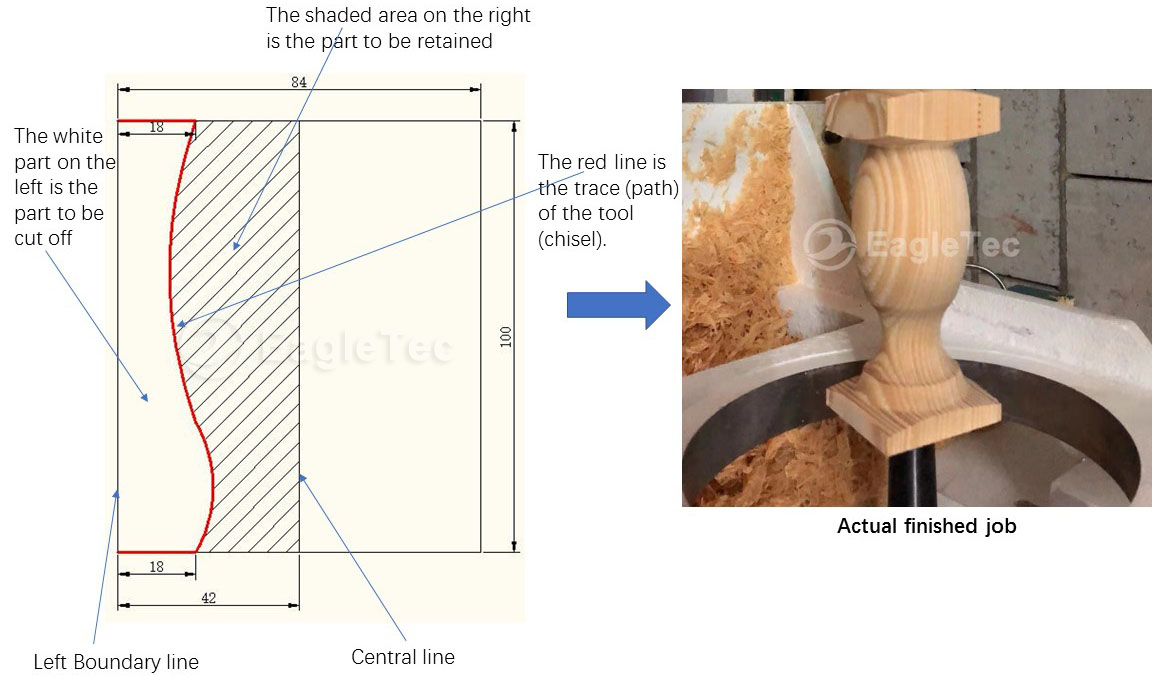
We just look the left half of the drawing, and please try to understand the points below.
The white part close to the left boundary line is the part to be cut off.
The shadow part close to the central line is the part to be retained.
The block red line is the trace (path) of the wood turning tools (chisel).
42mm is the half size of diagonal line.
18mm is the depth of first cut and last cut.
100mm is the total length of the design.
The above is the rule that should be followed in drawing. Let's take a look at the specific steps of the EagleTec wood lathe design drawing now.
Step 1. In AutoCAD software, select the line, open the orthogonal mode, draw two lines that are perpendicular to each other.

Step 2. Select the line in the vertical direction, click the offset, input value 42mm, press Enter, and click on the left side of the vertical line to generate the offset line. The new line here is the left boundary line of the drawing.

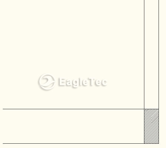
Step 3. Select the line in the horizontal direction, click the offset, input 100mm, press Enter, and click on the upper side of the line to generate the offset line. The new line here is the top boundary line of the drawing. How long you need to process, enter the appropriate value. For example, you want to process 100mm long, then input 100 here. So until now, we have determined the 4 boundaries of the drawing. The design will be drawn within the four boundaries, which is the space represented by the shaded portion of the image below.
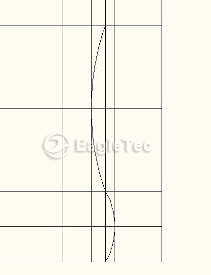
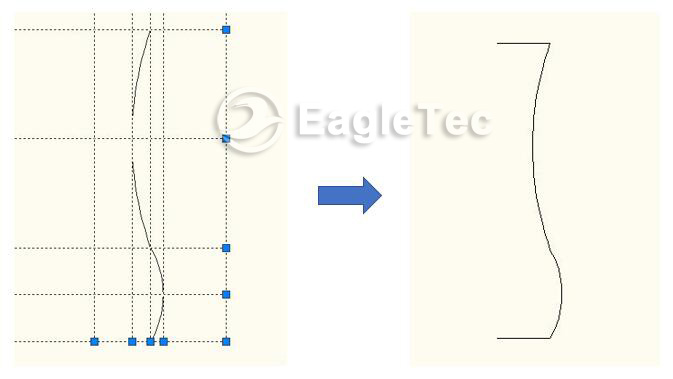
Step 4. Draw patterns inside the 4 borders according to your needs.
Step 5. Draw the bottom and top guide line. (process start and end)
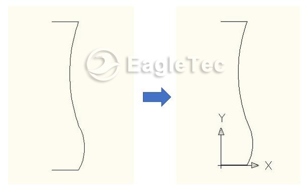
Now, the drawing can be taken to the wood lathe for process purpose.
If need any clarification, please feel free to contact us.
In next course, we are going to see some key points you need to know about cnc wood lathe job programming.
Original post from Jinan EagleTec Machinery Co.,Ltd.
【 Go Back 】 | 【 Close this window 】